


Now that the three main pieces of the guitar were mostly done, it was time to start putting them together and finish the construction of the instrument.
One of the things the Tundra Boy learned on his previous two instruments is how difficult it is to carve the inside of the body horns and the neck heel after everything has been glued together. There just isn't much space to get the file or sandpaper in the tight spots. Some of this can be attributed to the aggressive horn areas of the body shapes that he prefers. There's nothing wrong with the body shapes, they just present certain challenges.
To alleviate some of the carving headache, he opted to try and do as much as he could while the pieces could still be separated. That way he could look at the pieces when put together, decide the next step regarding what needed to be done, then separate them to do the actual carving. This made things a lot easier.
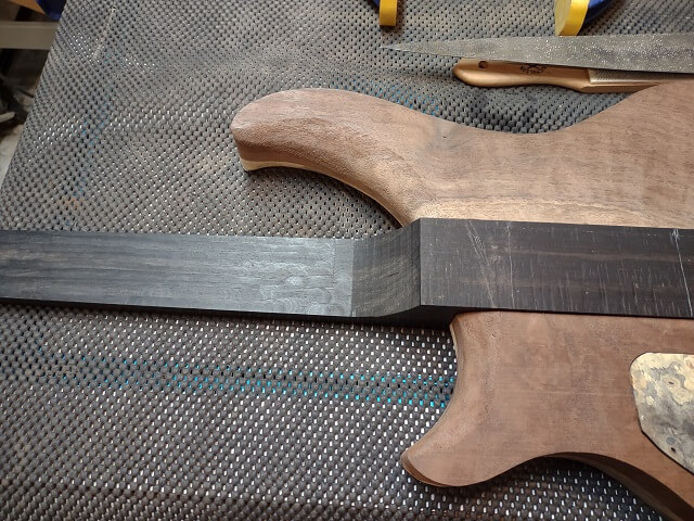
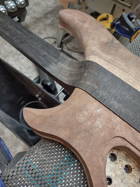
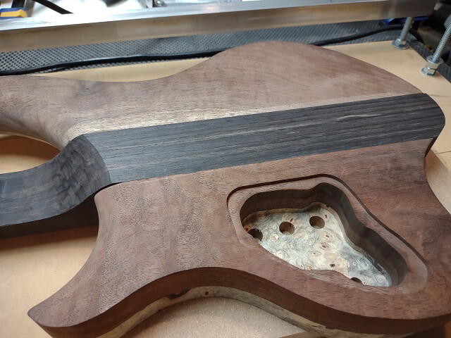
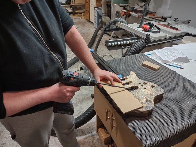
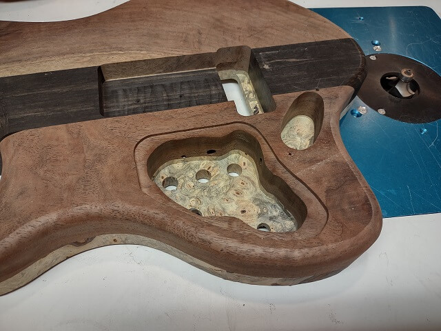
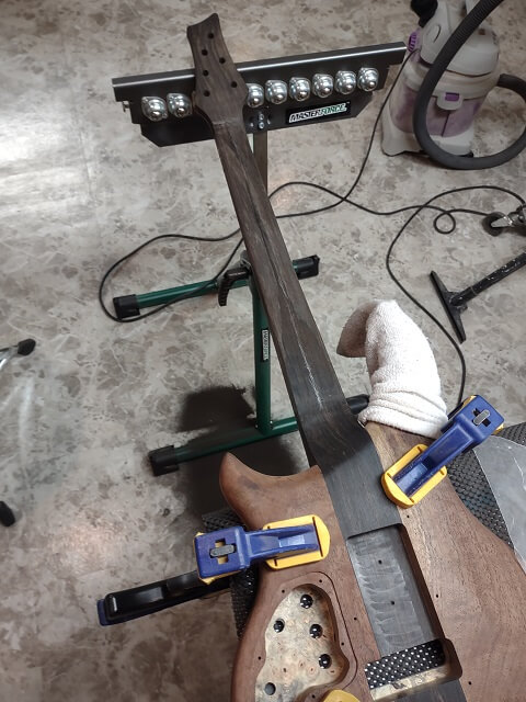
Final carving to the exact shape couldn't really be finished until everything is put together, but a lot of the work can be completed now. Here is the picture of the neck heel as the Tundra Boy was test fitting it. He made some pencil marks to guide him in carving. You can see how much wood needs to be removed from the neck before the heel will flow smoothly into the body.
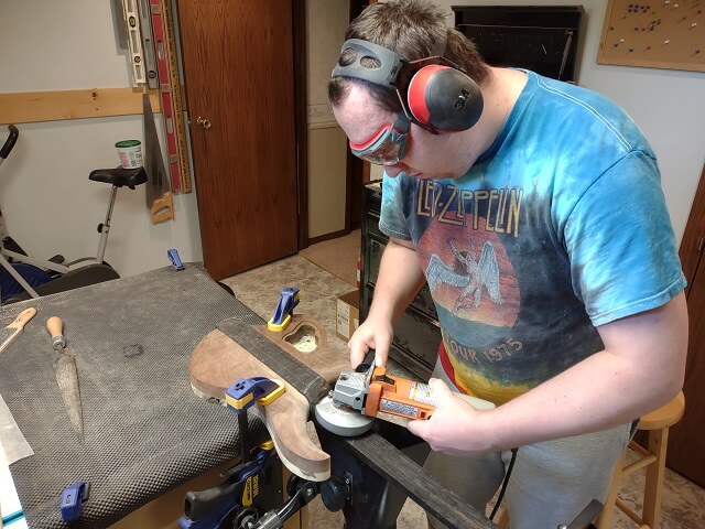
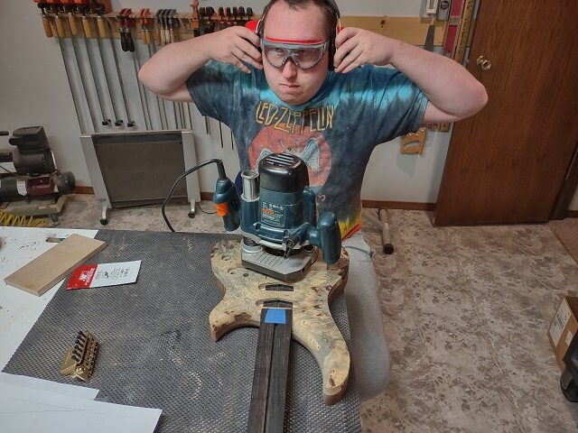
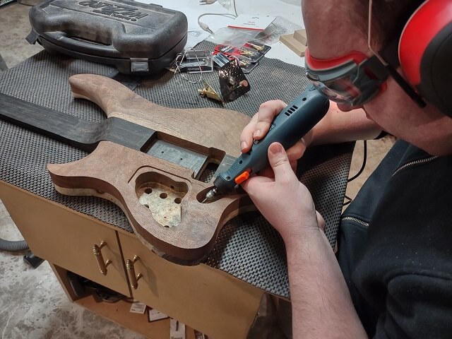
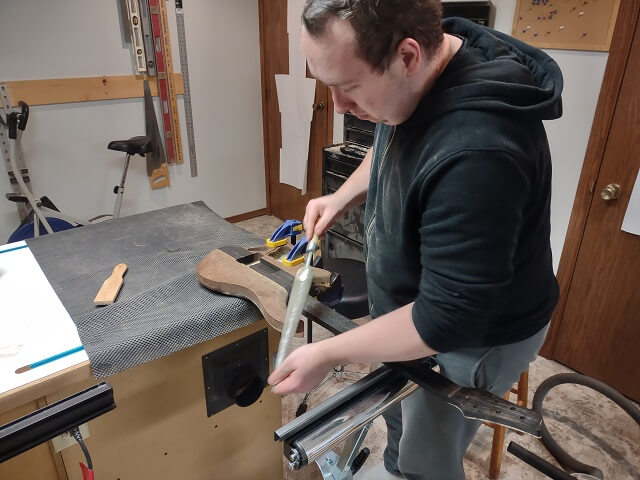
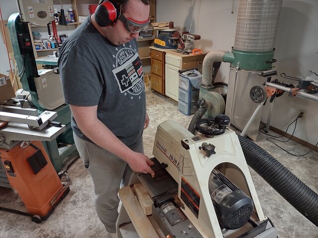
Because a lot of wood needed to be removed, the Tundra Boy opted to use a sanding disc in the disc grinder tool. This is a tool that needs great respect. While building his previous instrument, the Tundra Boy had a moment of inattentiveness with the disc grinder and removed the tip of his index finger. Thankfully he healed, but it was a lesson learned the hard way.
In addition to quickly removing appendages, a disc grinder will also quickly remove wood. It is an extremely aggressive tool, even when fitted with something seemingly benign like a sanding disk. The Tundra Boy went very slowly, making light passes as he carved away the excess wood. Note the dust hood to the lower right of the grinder. This was hooked up to the dust collector in a (somewhat fruitless) effort to keep the entire basement from having a layer of ebony dust covering everything.
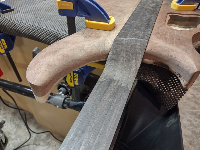
With the rough carving with the grinder done, you can see how much smoother the heel transition is into the body. One of the challenges with the design is that the neck heel is asymmetrical. The upper horn side rises to meet the body higher on the neck than the lower horn side does. There's no effective way to build a jig or guide to shape this area. Unless one resorts to using a CNC machine (which we don't have), carving areas like this needs to be done freehand.
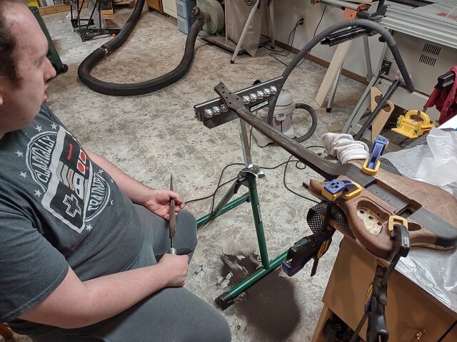
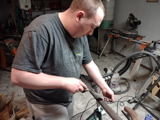
The grinder took the bulk of the wood away from the heel. The Tundra Boy then switched to the Dragon rasp to fine tune the remainder of the neck heel.
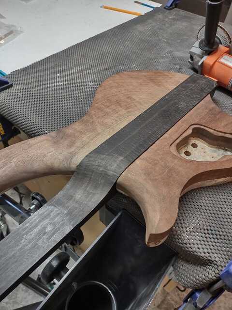
As stated, at this point the goal was to get the heel transition close. The rasp was used to get things as close as practical prior to gluing the neck in place.
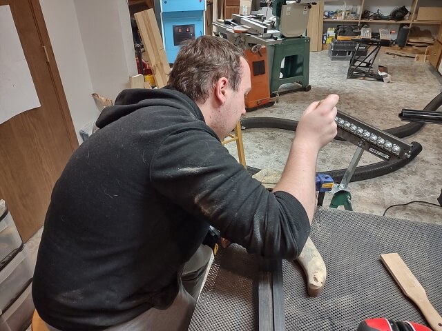
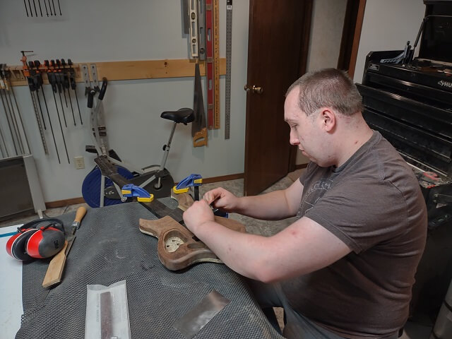
Here's a terrible picture of the Tundra Boy carving the neck heel. You really can't see much of what he's doing. But I took the picture so I might as well include it…
The remainder of the neck heel shaping will have to wait until the neck, body and fretboard are all glued together. But at least the bulk of the wood has been removed.
Pretty much everything that could be done while the pieces were separate had been completed. It was now time to glue the neck to the body.
This wasn't the worst glue-up we've ever tackled, but it certainly wasn't the easiest either. Before we had wet glue mixed up, we spent some time talking through the glue-up. We discussed how everything should get clamped, and in what order.
The Tundra Boy mixed up some epoxy, and I wiped down the ebony neck with acetone. Ebony is a very oily wood, so acetone is used to try and keep the oil from compromising the glue bond. The idea is that it removes oil from the surface of the wood. By the time the oil tries to seep back onto the surface, the glue has had time to set.
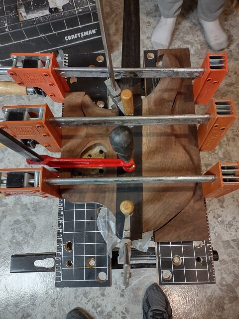
We worked together, spreading glue on the neck pocket of the underside of the body. Once the glue was spread evenly, the neck was carefully slid into place. We made sure the neck was tight against the front pocket, then clamped the back of the neck to the top. A piece of MDF was placed between the clamps and the buckeye top to keep the clamps from denting the soft wood.
After the neck was clamped to the top, horizontal clamps were added. This was to keep the body wings tight against the sides of the neck. Off-cuts from when the Tundra Boy cut out the body were used as cauls to give the clamps a flat surface to pull against.
Once everything was clamped up, the epoxy squeeze out was removed with a rag. The Tundra Boy didn't get ridiculous with the amount of epoxy he mixed up, so there wasn't a whole lot of excess glue seeping from the joints.
After 24 hours, the Tundra Boy removed the clamps and inspected the glue-up. There was one mystery glob of epoxy on the front of the guitar, but other than that everything appeared pretty clean. The joints all looked tight. We suspect that the mystery glob was glue seeping through a pinhole in the buckeye burl, but we're not 100% sure. It could have also been inadvertently smeared there as we were trying to clamp everything up. In any event, it could get easily removed with a little sanding.
With the neck glued to the body assembly, the back of the ebony neck was about 3/16" proud of the walnut body wings. This was intentional. We figured it was near impossible to cut the neck to the exact depth needed so it sat flush after getting glued in place, so it was left a little proud. Now that the neck was fastened we knew exactly how much ebony wood needed to get removed.
Most of the wood removal was done using my router sled jig. We spent a few minutes carefully setting up the jig so the router bit was (literally) a piece of paper higher than the walnut on all four corners where the neck was glued in. Then the Tundra Boy used the sled to route off the excess neck wood. I snapped a photo of the jig setup before routing started, but for some reason it wasn't on my phone. This has happened a couple of times now. Either my phone is having issues, or I think I'm touching the photo button and I'm not. I need to keep an eye on this.
The ebony was now level with the walnut body wings.
There was a little roughness from the router bit left. Because we were using a piece of paper as a spacer above the walnut, and a standard piece of paper is 100 microns (.1 mm) thick, we could sand the router scratches away and bring the ebony exactly flush with the walnut. The Tundra Boy did this using the ROS.
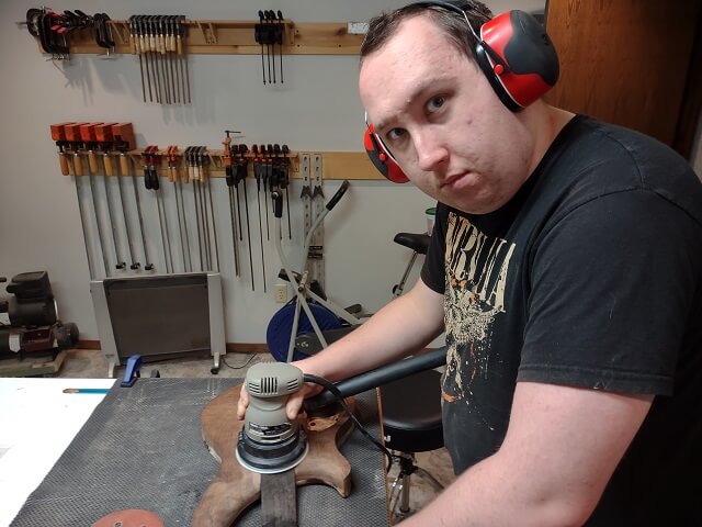
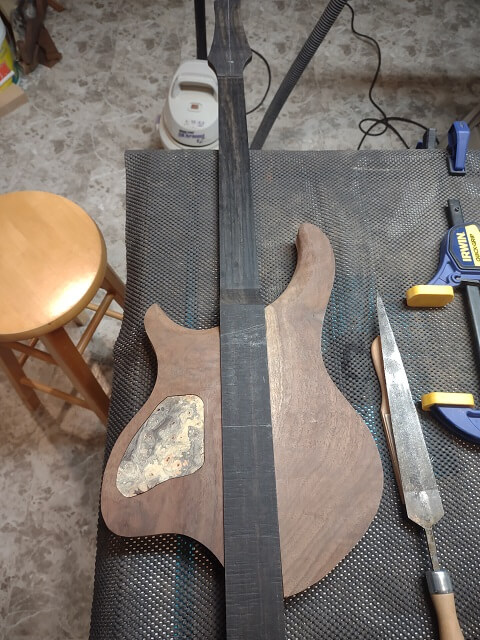
I know at the beginning of this project I wasn't a fan of using a solid piece of ebony for a neck-through. This resistance was due to weight, cost and conservation factors. But now that the ebony was sanded flush, I had to admit that it looks pretty darn nice next to the walnut.
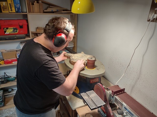
Similar to the back, the butt end of the ebony neck blank was also left proud. In this case it was left several inches proud. The Tundra Boy trimmed off the excess wood, and then used the oscillating spindle sander to bring the butt end of the neck even with the buckeye top.
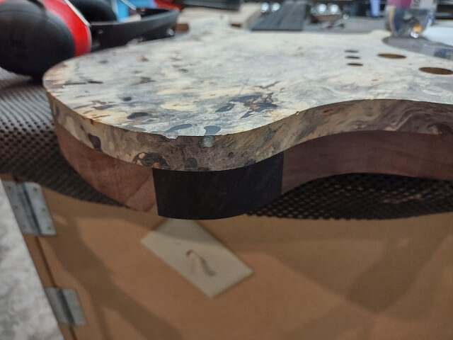
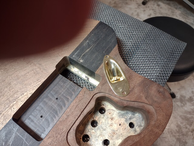
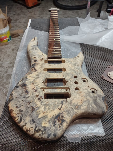
Here's the bottom of the instrument after everything was sanded to final shape:
Now it was time to route some pickup cavities. I went through the numerous pickup routing templates that I had collected over the years, and par for the course, none of them would work for the pickups being used.
The only single-coil pickup templates I had were part of larger templates for strat and tele style guitars. I did have a couple humbucker templates, but they were way too large for the Wilde Bill L500 pickup. The template would have worked, but the Tundra Boy wants his pickups to be directly screwed into the guitar wood with no mounting rings.
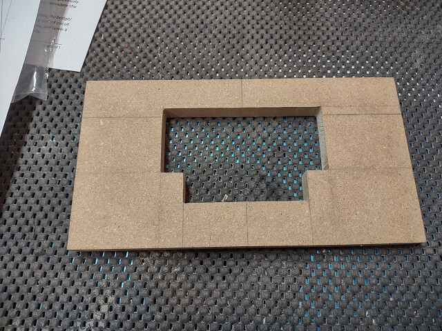
Mounting rings allow the pickup routes to be larger and/or not exactly perfect. Any gap or imperfection will be covered up by the pickup ring. Without these rings, standard pickup routing templates leave a cavity that is much too large to look good. So, we were going to have to make new routing templates that would make a hole just slightly larger than the actual pickup.
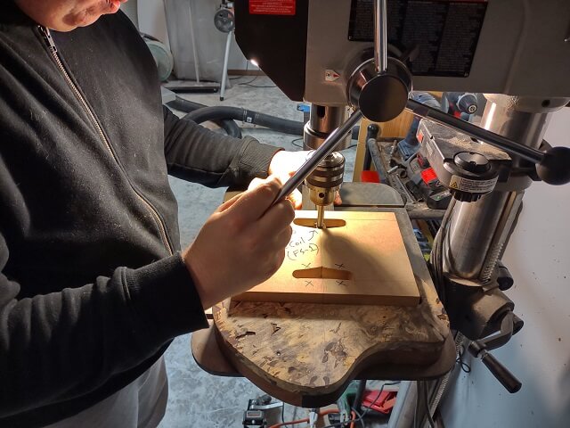
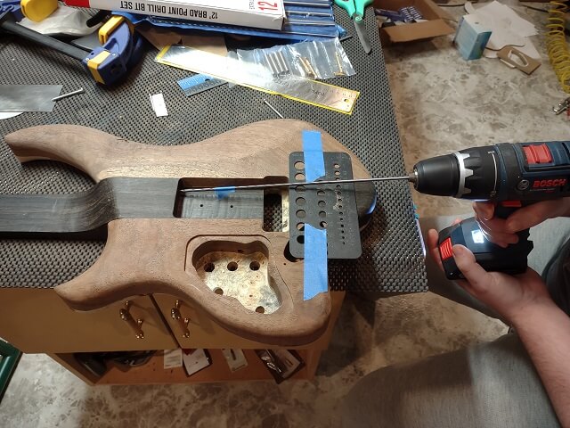
We did some measuring and drawing, and came up with a couple of patterns. One was for the two single coil pickups, and one was for the humbucker. We noticed that both types of pickups had rounded edges that were 3/8" in radius. Rather than trying to scroll out all of these corners exactly, the Tundra Boy opted to drill them with a 3/4" forstner bit. That way all of the curves would match identically and there wouldn't be that "wonky" one that haunts him every time he looks at the guitar.
Then the Tundra Boy then carefully cut the template middles out at the scroll saw.
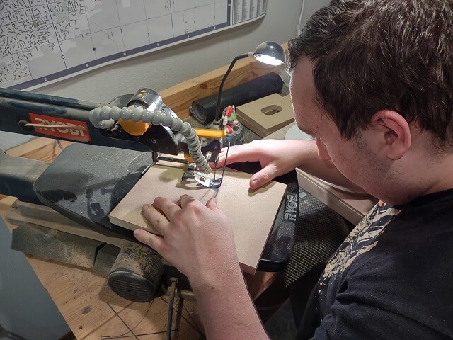
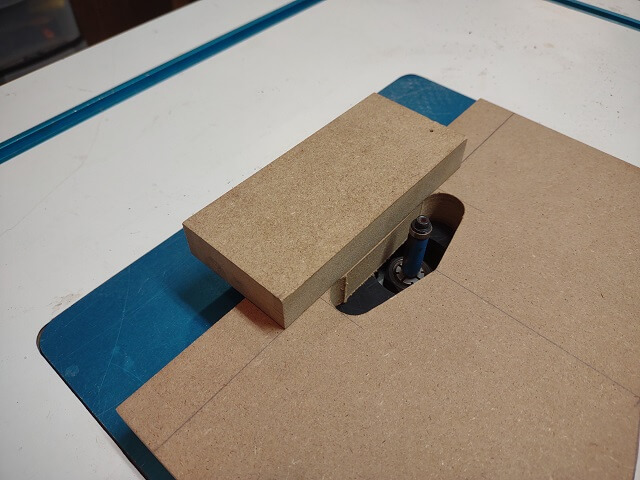
Pickups tend to have straight flat edges. If the template edge isn't also straight, it becomes quite noticeable when the pickup is placed into the cavity. In order to keep the template edges as straight as possible, the Tundra Boy just scroll sawed close to the line. Then a flat piece of MDF was taped to the line and a flush trim bit on the router was used to make it perfectly straight.
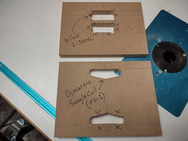
Here are the two completed pickup templates. You can see that both of them took two attempts to get perfect. The failed attempts were clearly marked so that they didn't accidentally get used.
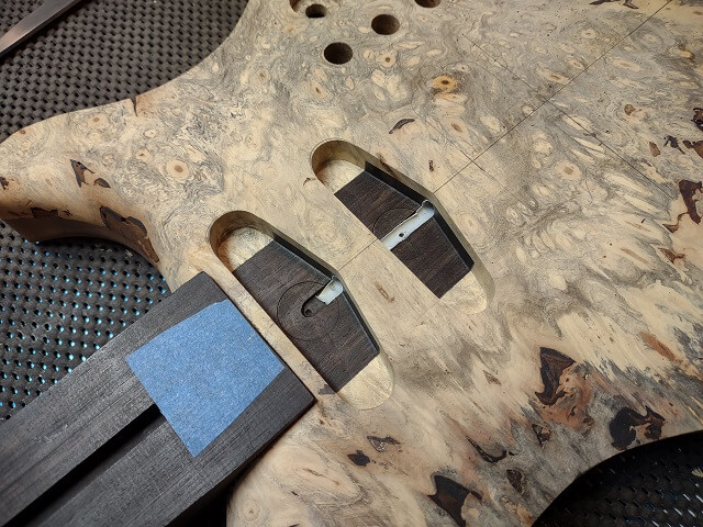
The top of the neck pickup was going to be located 1/4" from the end of the fretboard. The face of the neck where the fretboard is going to be attached sits 1/8" proud of the top of the body. In order to allow the template to sit in the proper location, the Tundra Boy had to route away an 1/8" deep channel on the back side of the template.
We then took some time to layout where on the body the pickups would be located. There's not a lot of space for three pickups between the end of a 24 fret fingerboard and a Floyd Rose bridge. The front edge of the Floyd is located 1/2" closer to the fingerboard than the actual scale length location (25 1/2" scale length means the pivot points of the Floyd get drilled at 25".)
I was all worried that there wouldn't be enough room for three pickups in this small space. The Tundra Boy was insistent that there was plenty of room. Once we marked everything, he was proven correct.
I'm not sure what was happening this particular weekend, but I was having a lot of trouble with spatial estimation. Distances and measurements that I could normally get pretty close by eye were proving difficult to me. We would drill or route a 1/4" deep hole, and for some reason it would look deeper or shallower to me, causing me to grab a measuring device to reassure me that the hole was indeed 1/4" deep. The Tundra Boy even remarked that I was pretty "off". Hopefully that was an isolated weekend phenomena and not a permanent brain shift.
It took an entire evening to make the two pickup templates. It seemed like a non-productive evening, but in actuality it was very productive. I think it just felt like not much got done because nothing on the guitar itself changed during this time.
Also, the first game of the 2023 World Series started on this evening and we wanted to keep an eye on the game as we worked. Unfortunately, the digital converter for the TV in my shop decided to die this same evening. We had to spend some time swapping it out and then getting the replacement activated with the cable company. So that sucked up some additional time. I'm glad we did, though, as it was an exciting game. The score went back and forth and wound up going into extra innings, with the Texas Rangers finally walking off the Arizona Diamondbacks.
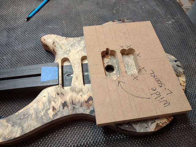
The next day, we were ready to start routing pickup cavities.The Tundra Boy attached the single coil template with double-sided tape in the proper location for the neck pickup. Then we did a "sanity check" with measuring devices and figured out the hole in the template was off about two millimeters to the right from where it should be. We removed the template and did a whole bunch of measuring.
After a bunch of checking and rechecking, we figured out there were two very minor problems that combined threw off the template placement. First, one of the lines down the edge of the template that we use to line up the template with the lines marked on the guitar was off ever so slightly. This got erased/sanded off, and a new line was marked in a more accurate location. Second, the center line we drew on the top of the guitar was off just a hair. That too was erased and redrawn.
With those two issues corrected, the template was retaped and upon checking the measurements, everything now looked correct. Whew!
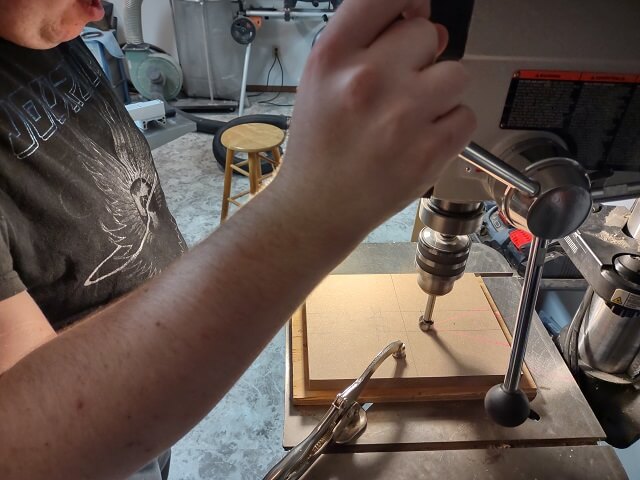
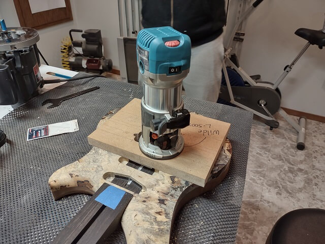
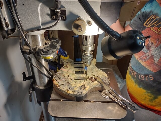
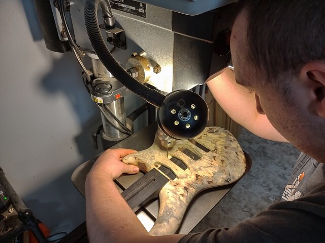
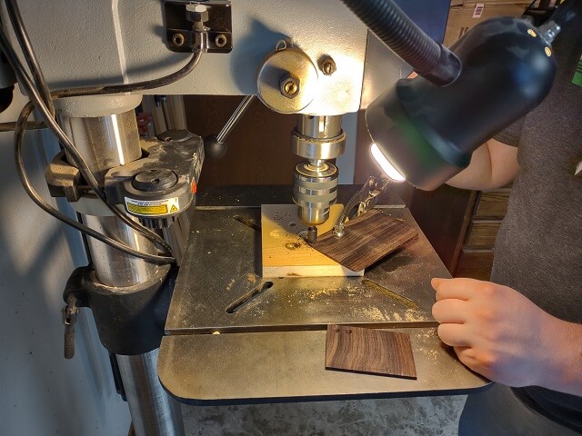
As we usually do, in order to reduce routing and save wear and tear on expensive router bits, the Tundra Boy drilled out the excess waste wood using the drill press.
Then using a pattern cutting bit, he routed the pickup cavity. The cavity needed to be 1/2" deep, so he did it in two passes removing 1/4" of wood at a time.
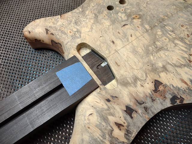
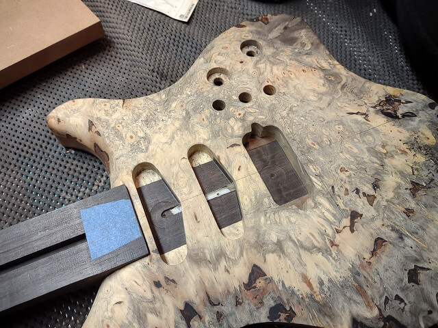
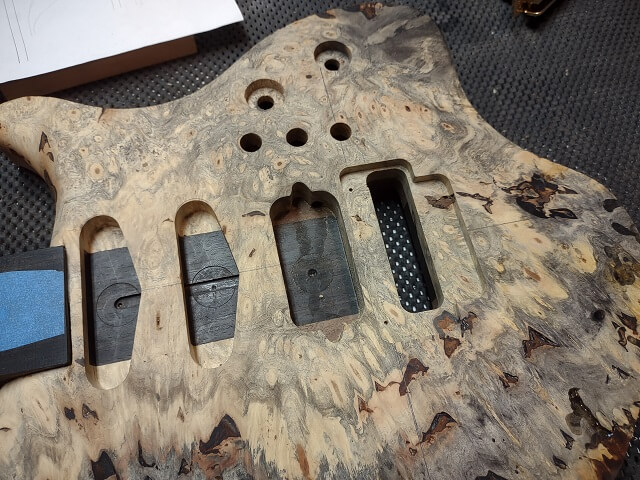
Removing the template revealed that the pickup route was a resounding success. It lined up with the end of the neck, indicating it was straight. There was no tear-out requiring repair. And the plastic drinking straw conduit was revealed as intended.
The same template was then carefully positioned at the spot we had marked for the middle pickup, and the process was repeated. And for a second time in a row, the routing was successful.
The single-coil pickup template was placed in the pickup template graveyard, along with all the others on the shelf. Perhaps one day it will be needed again if I happen to use a pickup of the same dimensions. But as noted above, it seems like every pickup and use-case is just different enough to warrant a new template.
The bridge pickup template was attached and verified to be positioned correctly, and then the drill press was used to establish the final depth and remove some of the excess wood.
Routing went smooth. This pickup route had a slightly different requirement than the previous two. The humbucker had two "ears" that will be used for mounting the pickup. The ends of these ears have a radius of 1/8", which is too small for the 1/2" pattern cutting bit to carve. So, before the template was removed, a special tiny 1/4" pattern cutting bit was used to route out these sections.
This tiny bit was very expensive to purchase, so I try to treat it with kid gloves. The routing went slow, only removing about 1/8" of wood with each pass.
Also, we used a different router with this little bit. This was mainly due to issues with the larger routers. My old workhorse Skil router that I've had for almost 30 years tends to have bits seize up in the collets, requiring tools to pry them loose. I didn't want to risk damaging this pricy router bit. My dad's old Black and Decker router doesn't have this issue, but because of the way it was designed visibility can be a problem, especially when routing deep cavities.
So we used my Makita mini-router. This provided good visibility and a non-sticky collet, with the trade-off of a finicky adjustment mechanism. It seems that no router is perfect.
With the "ear" routes complete, the template was removed. The third pickup cavity route was a success.
Routing pickups always makes me nervous. I've had things go wrong, and the nature of where they are located means that when problems do happen it's in an extremely visible place. I breathed a huge sigh of relief when all three pickup routes were successful. I don't know if the Tundra Boy had felt the same pre-routing angst as I.
Now a much simpler operation could be done. The wiring for all three pickups will pass into the control cavity from the bridge pickup route via a hole. To drill this hole, an aircraft bit was used. The need for the aircraft bit was due to the weird, shallow angle required. A piece of thin wood was placed on the top of the guitar just to keep the bit from marring the surface should it accidentally come in contact.
The next day we started on the Floyd Rose bridge routing. This is a complicated route that has to be done in four separate steps.
A couple years prior I had purchased a Floyd Rose routing template from Stewart MacDonald guitar supply. Stew Mac provides high quality products and great service, but generally comes with a very high price tag. The template set cost $60, and didn't come with a template for the front recess.
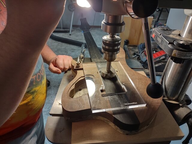
Anyway, regardless of my woes about what I paid for the templates, we were able to use them for this guitar. The first template attaches to the top of the guitar with a couple of screws that are conveniently located in the exact same place that the bridge pivot posts will also be located. Holes were drilled and the template was screwed in place.
The sheet that came with the bridge template instructed us to drill a 1/2" hole in the corner of the template all the way through the back of the guitar. This hole will then be used as a reference point to line up the rear template.
Back on the front of the guitar, the excess wood inside the template was drilled out before routing commenced. We noticed that the buckeye drilled easy, but once the bit hit the ebony we would see lots of smoke, even when trying to go slow.
Then the Tundra Boy did the first bridge route. This hole was for the bridge block, and was routed to a depth of 1 1/8". He did it in increments of about 1/4" per pass. After the first couple of passes the template was removed and the guide bearing was just run right up against the top of the previously routed area.
With the bridge block route complete, the guitar was flipped over and the rear spring cavity template was taped to the guitar. The template had screw holes for mounting, but unlike the front template where the screw holes would align with holes that would eventually be used for the tremolo posts, the screw holes in the back would just be extra holes in the guitar. We didn't see any reason to drill unnecessary holes, so that's why we opted to use tape.
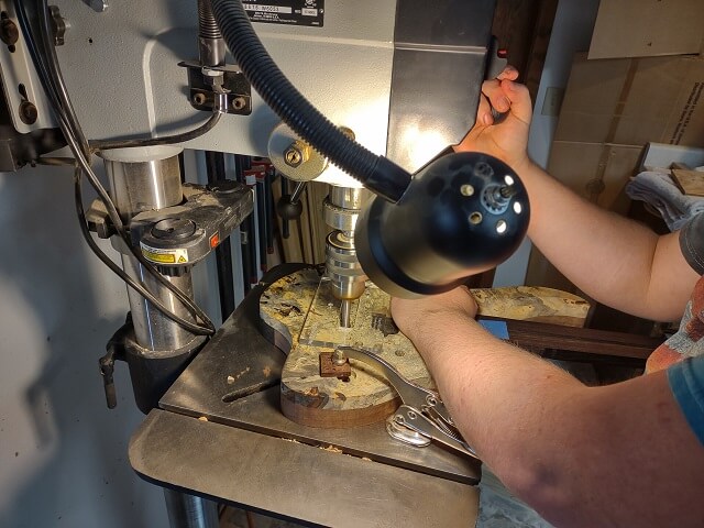
The Tundra Boy drilled out the extra wood with a very large 2" forstner bit. I slowed down the drill press speed for this large bit (note to self: return the drill press to the usual speed to which I keep it set.) A bit this large in ebony generates a lot of heat. And I mean a lot of heat. After drilling the first hole, the Tundra Boy accidentally bumped the drill bit with his finger and wound up receiving a noticeable burn mark. Ouch!
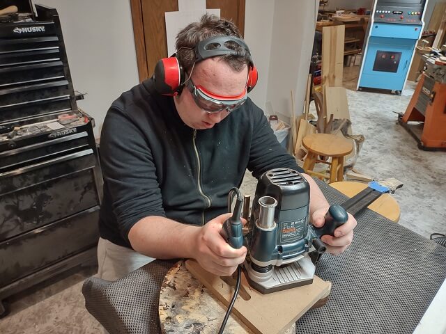
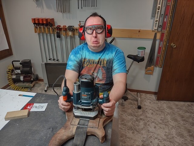
Back at the workbench, the rear spring cavity was routed to a depth of 5/8". Either the Tundra Boy was really nervous about routing this cavity, or he was hamming it up for the camera. You get to decide.
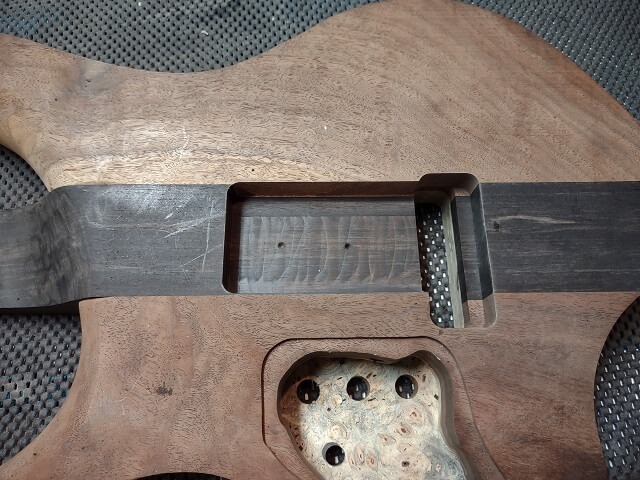
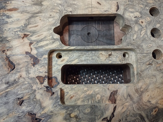
Here is the second of the four Floyd Rose routes complete. This route connected with the cavity for the bridge block, and because it severed the ebony neck completely, technically it turned this guitar into a long-tenon rather than a neck-through instrument. But for all practical purposes we're still considering it a neck-through.
The version of the Floyd Rose bridge that the Tundra Boy opted to use is called the NFT, which means "Non Fine Tuner." It is a reissue of the first generation Floyd Rose bridge that was used on the Hentor Sportscaster, which is one of the guitars the Tundra Boy is using as inspiration.
The Tundra Boy wanted a front recess to allow the bridge more room to pull back on the strings. However, a front recess routing template for the NFT bridge was not available from Stew Mac. In fact, after some internet research, it is not available from anyone. There just aren't enough of these bridges out there for someone to produce a front recess template.
So, we would have to design our own. I measured the bridge, and called out the measurements to the Tundra Boy who then drew the lines on a piece of MDF. All the marks were double-checked for accuracy, then the Tundra Boy cut the template out on the scroll saw.
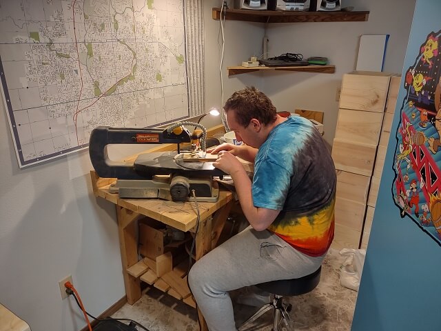
We thought about using the "cut near the line and then route it perfectly straight" technique, but with all the different sides of this route it would mean taping and routing seven different times to get them all. That seemed tedious. Instead, the Tundra Boy just opted to carefully follow the marked lines exactly with the scroll saw.
I must say, the Tundra Boy's scroll saw skills are drastically improved from when he first started a few years ago. Back when he was beginning to learn how to scroll, it was difficult for him to accurately follow a line. When he finished cutting this template, I was impressed. Without being told otherwise, most people wouldn't suspect that all these lines were cut freehand.
The template was fastened to the guitar with double sided tape. A couple other pieces of scrap MDF of the same thickness were also taped down just to give some extra support for the router. Then the Tundra Boy began to route.
It went mostly without a hiccup. I say mostly, as once the route was complete there was a minor incident that happened when I was cleaning up the wood chips using the dust collector hose, and suddenly the hose sucked up one of the pieces of MDF being used for support. Not wanting this chunk of wood to hit the impeller, I ran across the shop and killed the power to the dust collector. Then we spent a few minutes trying to figure out where the chunk of wood ended up. Eventually we discovered it had wedged itself sideways inside the hose, just about two feet from the impeller. That was close!
With the crisis over, the template was removed to reveal the completed front recess.
Now it was time for the fourth and final Floyd Rose bridge route. This route was again from the back, and was just to deepen the back of the spring cavity to within 3/16" of the top. This will give room for the bridge block to move when doing "dive bombs."
The bridge routing was done. The only thing left was the holes for the bridge mounting posts. These need to be drilled extremely accurately, as even a half millimeter variance will cause tuning issues.
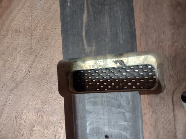
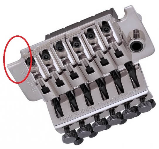
Newer versions of the Floyd Rose bridge have one "U" shaped blade, and the other blade is flat. This was done to reduce the ridiculous accuracy needed in the post spacing. One post will self-center on the "U" side, and the blade will let the other side pivot anywhere the corresponding post is located. Here is an example picture with the flat blade side circled:
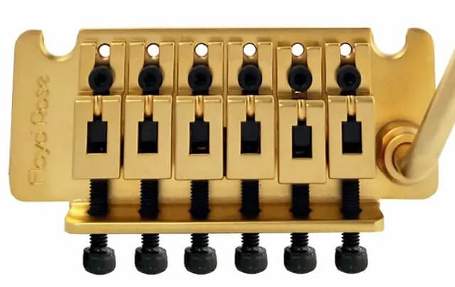
This being a reissue of the original Floyd Rose bridge, both of the pivot points are a "U". Here is a picture of the NFT bridge where both of the pivot points can be seen:
So, how do we accurately drill the holes for the mounting screws? Well, as already mentioned, one of the benefits of the Stew Mac routing template was that the template mounting holes line up exactly with the Floyd Rose bridge. So we already had holes drilled in the correct location, they were just a smaller diameter than what was needed.
The next challenge was, how do we accurately enlarge these holes from the current 5/32" diameter to the needed 3/8" diameter? After pondering it a moment, we decided to use the following method:
First, the existing 5/32" bit was chucked into the drill press. Second, the guitar was clamped to the table in the exact spot to allow the 5/32" drill bit to lower into the existing holes without bending. Third, without unclamping the guitar, the bit was changed to the 3/8" diameter bit. And finally fourth, the larger hole was slowly drilled to proper depth in the exact same position.
It was a little tedious, as the drill bits had to keep getting changed, but it seemed to work well.
Just to make things more difficult, the top quarter inch of the freshly drilled 3/8" screw holes had to be enlarged once again to 9/16". The mounting post screws had a 9/16" shank at the top that would need to fit partially down into the holes. So the above process was repeated again to enlarge this small portion of the screw holes.
Once the spring claw is installed, it will have a wire soldered to it that will provide the ground for the electronics. That wire will connect to the other ground wires in the control cavity. To pass the wire from the rear spring cavity to the control cavity an 1/8" hole was drilled.
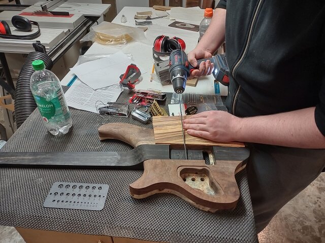
It was time to figure out where the output jack plate would be located, and how the hole for it would be shaped. There was much spirited discussion about placement. Then the method of shaping was discussed.
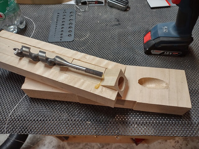
Back when I built the walnut flying-V guitar I installed a strat-style output jack plate on the back of the guitar using a low-angle drilling jig I made along with a 1" auger bit. We thought about this option for this guitar, and even went as far as pulling the jig out of storage and giving it a test run on some scrap wood.
The results were mixed. It did create the hole that was needed, but it also seemed to hack chunks out of the wood rather than smoothly shape the hole. It appeared to be a little too aggressive of a method when working with expensive wood that has already had a ton of hours invested to get it to the current state. I made the executive decision that this was not the correct jig to use, and even went as far as deciding to dispose of the jig. I just can't see myself ever using this jig again in the future, so there's no need to keep it around collecting dust. I took one last picture for memory purposes, and then tossed the jig in the trash.
So, if we weren't going to use that jig, then we needed to come up with a different plan for the output jack hole recess. We decided that routing would be the cleanest option, but that would require a template.
I had a complete Strat body template that included the hole for the output jack, and we thought about using it. However, because of where that hole was located on the Strat template combined with where the hole needed to be located on this guitar, the bulk of the Strat template would be left hanging unsupported off the face of the guitar.
Also, the output jack hole on the Strat template had a chunk missing from the edge where I accidentally hit it with a spinning router bit.
So we opted to make a new template. A fresh piece of MDF was cut in a size large enough to support a router on all sides. The hole from the Strat template was traced onto this piece of MDF. The portion of the shape where the chunk was missing was redrawn. Then the Tundra Boy cut out the new template on the scroll saw.
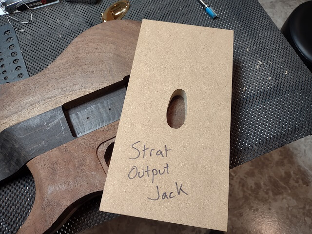
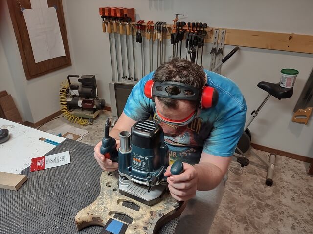
The template was taped in place on the guitar, the excess wood was removed at the drill press, and a pattern cutting bit was installed in the router. The Tundra Boy then prepared to route the hole.
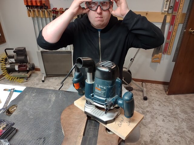
The route needed to be 1 1/8" deep, so it was done in about four passes. After the third pass, the router had reached maximum plunge depth, so the template was removed and the hole was brought to final depth by running the router bearing against the upper edges of the routed hole.
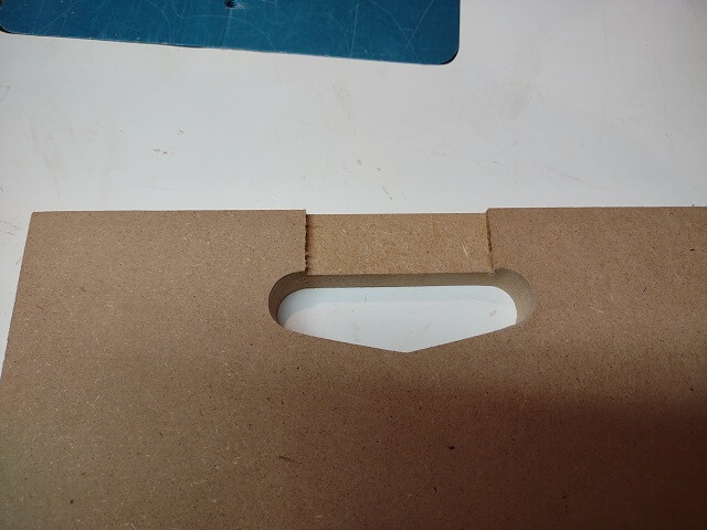
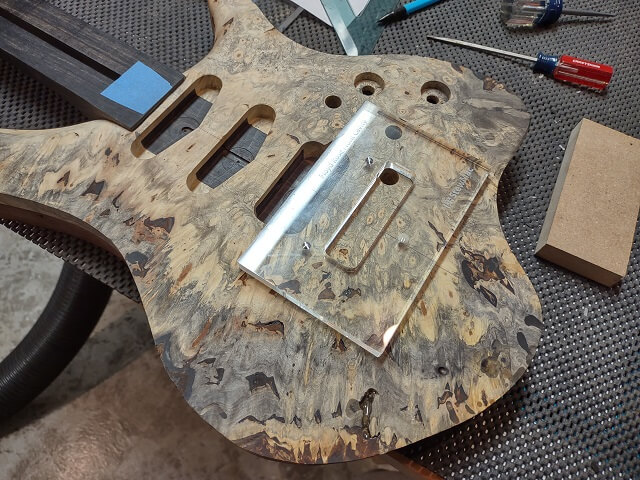
The routing was a success, and the output jack plate fit well. One little detail I've learned with Strat style output jack plates is everything can fit well until you insert a cord into the jack. The tip of the jack often protrudes just a wee bit farther than the end of the jack. The end of the jack is generally right up against the edge of the chamber routed. So basically, once mounted the wood will keep the guitar cable from plugging all the way in.
The solution to this is to use a dremel tool and lengthen the side of the route down where the tip of the guitar cable will be located. This wasn't an exact operation. The Tundra Boy just freehandedly removed a few millimeters of wood down in this area.
A hole needed to be drilled so the wires from the output jack could get into the control cavity. The Tundra Boy drilled this hole with an aircraft bit.
Most of the front and back edges of the guitar will be carved. The area on the back around the control cavity and output jack, however, will not be carved. This is due to the depth needed for the controls, and because carving into the cavity area would quickly go through the thin control cavity cover.
However, just having a square edge in this area isn't ideal either, as it wouldn't look very good. So the Tundra Boy opted to use a 3/8" roundover bit to shape the edges in this area.
He actually shaped the edge much farther in each direction than just the areas that need the roundover. These areas will get carved away, but having the roundover extending into them will let him carve a smooth transition to the rounded portion.
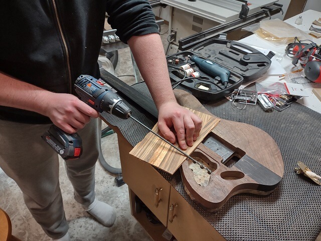
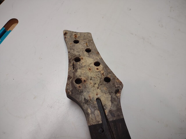
One thing that probably should have been done before the top and body wings were glued to the neck was drill the holes in the headstock for the tuning machines. Doing it now meant that there was a lot more weight to the guitar hanging out in space as the holes were drilled. Not ideal, but not an insurmountable issue, either. I supported the weight of the guitar body while the Tundra Boy positioned the headstock and drilled the holes. Because my hands were full I didn't get a picture of the actual drilling process, but here's the completed results:
Now the carving of the front and rear edges of the guitar could be done. This process is more art than science. The Tundra Boy spent several hours with my dragon rasp shaping the edges to his satisfaction.
The rasp leaves a very rough surface. Before sanding, the Tundra Boy used a scraper to smooth the surface a bit and further refine the shape of the carved areas.
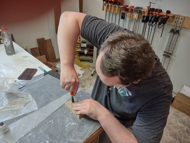
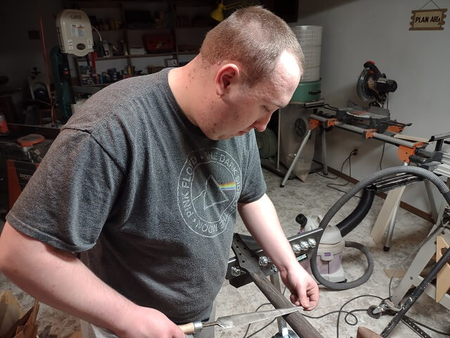
The tremolo cavity needed holes for the spring claw screws to be drilled. These are tricky holes to drill because of the extremely shallow angle. An aircraft bit is a must. Also, the screws needed a 4.5 mm hole (or 11/64").
For these holes, most builders just use a 1/8" drill bit and call it "close enough." The holes are a little small, but once you muscle the screw into place once it will work. For this guitar, however, the screws were going to be driven straight into solid ebony. We had a big concern about our ability to muscle the screws in without stripping the screw heads.
So, I went on the hunt for either a 4.5 mm aircraft bit, or the imperial equivalent. As it turns out, these are really hard to find. I was able to find metric bits in 12 cm lengths, which was too short. I eventually located an 11/64" bit that was a full 12" long, but unfortunately it came in a set of 10 bits. And also unfortunately, the reviews led me to believe the bits were of dubious quality.
Not having many other options, I went ahead and purchased the set. The remaining bits duplicated sizes I already had in my stash of drill bits, so I'm not sure when they would get used.
The Tundra Boy took his time and slowly drilled the holes. Because the reviews stated a few people had the bits snap while in use, he would slowly drill about 1/4", and then pull the bit out to let it cool. The last thing we wanted was to have a drill bit break off inside the ebony, and then have to do major surgery to attempt to remove it.
Next, the pickup mounting holes were drilled. This seemed like a pretty straightforward operation, but we managed to drill one off center which resulted in having to fill the hole and re-drill. At least the mistake will be hidden underneath the pickup so nobody will ever see it.
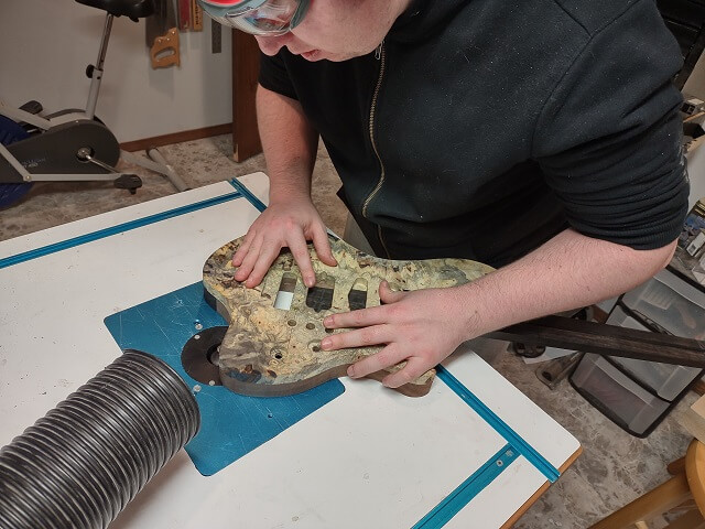
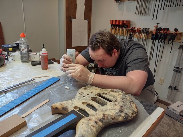
With all the control cavities routed, now the Tundra Boy could focus on filling the remaining voids in the buckeye burl. There were a ton of them.
Many of the voids and holes wrapped around curved areas he had carved. While filling, the Tundra Boy learned that the clear epoxy filler he was using was quite a bit thinner than structural epoxy. Unless the surface was perfectly flat, the epoxy would run out of the hole and down the edge of the guitar, rather than filling the area.
That was a frustrating situation, and initially attempts were made to angle the instrument so that the holes were oriented to be level. Given all the curved surfaces on a guitar, this proved virtually impossible.
Instead, the Tundra Boy figured out a trick. He would mix up a little bit of epoxy, then wait for it to "kick" as the chemical reaction started. The epoxy would get warm and start to thicken. At this point, he would quickly spread it into the voids in the guitar where it would harden before it had a chance to run. This worked, but given the 45 minute open time of the epoxy between mixing and kicking, there were long periods of sitting around staring at the wall.
The whole filling process was very tedious and took probably about 10 different fill/sand sessions. The Tundra Boy quickly discovered that he would fill a void with epoxy, then when level sanding it, the sanding would open up new holes in the wood that needed to be filled. Eventually he reached a point where he cried "uncle" and decided to live with a few pinholes that remained, as he couldn't sand the filled areas without creating more pinholes.
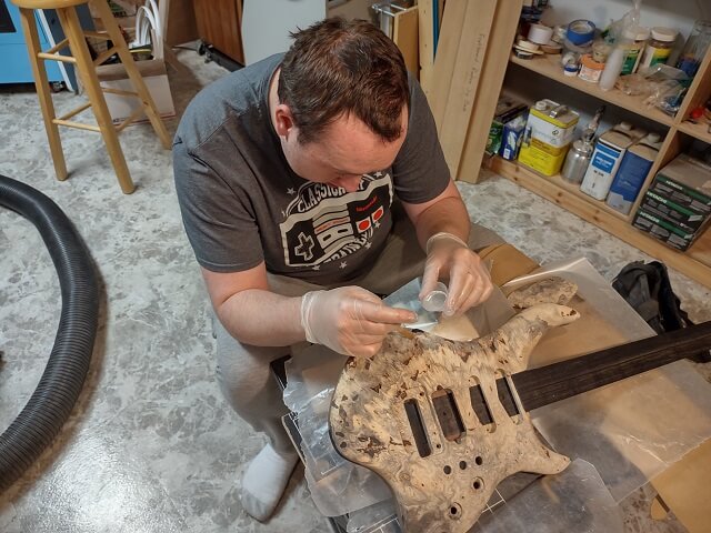
Buckeye burl is a very pretty wood, but the Tundra Boy has decided he's never using it again. It's just too much of a hassle.
To kill some time In the midst of filling the buckeye burl, the Tundra Boy worked on making a cover for the rear tremolo cavity. He used some of the leftover Brazilian rosewood, which means this will probably be the most expensive tremolo cavity cover ever made.
At 1/4" the piece was a little bit thick, so he thinned it using the drum sander down to a more reasonable 1/8" thick.
Because of the odd placement of the output jack, the tremolo cavity cover couldn't be left perfectly rectangular. One of the corners needed to be trimmed at an angle, and the corresponding mounting screw hole needed to be moved over. This took a little bit of thought in order to get the corner cut accurately.
The holes were drilled for the mounting screws, then the screw holes were countersunk to make them look neat and professional.
While he was at it, the Tundra Boy also drilled the holes for the control cavity cover. The buckeye burl cover was so soft that we were worried that using the drill press to countersink the holes would be too aggressive. So, he just countersank the holes by hand. It was pretty easy going in the mushy wood.
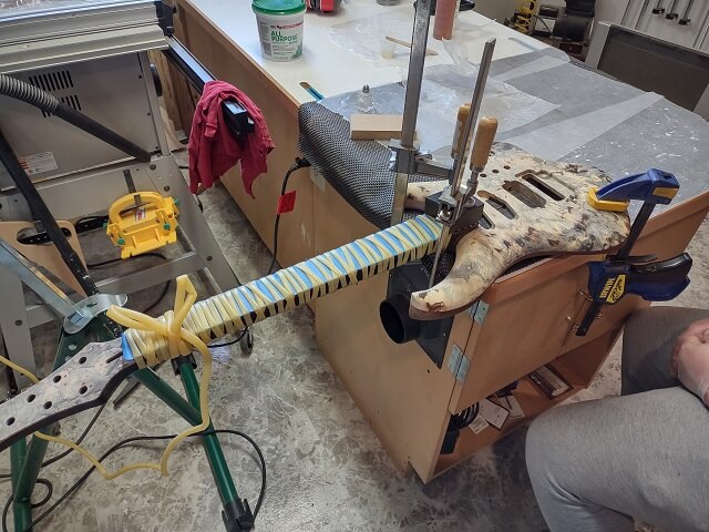
After what seemed like an eternity, it was time to glue the fretboard to the neck. The Tundra Boy taped the face of the fretboard for protection during the gluing process. He didn't want some errant glue on a finger to accidentally smear across his nicely sanded fretboard.
The Tundra Boy mixed up some slow-set structural epoxy (System Three T-88). I always use epoxy to attach fretboards, as I've had the moisture in PVA glue cause neck backbow issues. The Tundra Boy set a timer and mixed the epoxy for at least five minutes.
The typical procedure was followed: The truss rod was put in place, then a piece of masking tape was run over the top of the truss rod channel. The mixed epoxy was then spread on the neck, then the tape was removed and the fretboard set in place. This keeps the glue from spreading too far once the fretboard is attached and gluing the truss rod in place, which would render it useless.
For clamping, we decided to try something new this time around. I had purchased 30 feet of surgical tubing to use in lieu of traditional clamps. The idea is that the tubing will naturally keep the fretboard centered on the neck, and the tubing will conform to the odd shape of a neck better than bar clamps.
The Tundra Boy was skeptical that surgical tubing would provide enough clamping pressure. To demonstrate, I stretched a couple of wraps around his arm. That was enough to sway his opinion.
Before we committed to this clamping method, I had a concern about the use of surgical tubing with epoxy. I knew that PVA glue doesn't stick to the rubber, but I wasn't sure about T-88. The last thing I wanted was to accidentally glue the tubing to the guitar neck. A few weeks prior to gluing we did a test gluing making sure to smear a lot of glue onto the tubing. Much to my relief, the epoxy didn't stick to the tubing in the least.
The Tundra Boy held the fretboard in place as I stretched and wrapped the tubing around the neck. I stretched the tubing very tight in order to exert lots of clamping pressure. I went down the neck with a wrap about every 2-3 inches, just to get the fretboard held in the proper location. Then I came back down the neck with additional wraps about every 1/2" or so. I tied the remaining tubing in a bow so it could be easily pulled loose the next day.
The very end of the fretboard over the body was in a place where the tubing wouldn't reach, so we used a couple of bar clamps to hold that part of the fretboard down.
Not knowing how much surgical tubing I would need, I had purchased 30 feet. As it turned out, 15 feet would have been plenty. Maybe even 10 feet. I didn't account for how much stretching was involved, which effectively doubled or tripled the length of the tubing. In any event, I had a lot of unused tubing left over. Oh well, the stuff is pretty cheap,
Once dry, the tubing easily unwrapped from the neck. Overall, using the tubing was easier than my old method of bar clamps and wood cauls. I will likely use this method going forward.
In the excitement of using the new clamping method, one thing we forgot to do was wipe down the rosewood fretboard and the ebony neck with acetone before gluing the pieces together. We do this because these are oily woods, and sometimes the oil can interfere with the glue adhering to the wood. Oops. As I've mentioned already, the Brazilian rosewood was particularly oily. Thankfully, the fretboard seemed to be securely attached so I think we dodged a bullet.
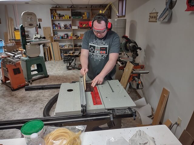
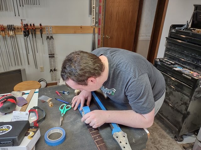
Now it was time to carve the neck. The Tundra Boy marked a center line with white pencil down the back of the neck. The neck had already been routed to the desired thickness, so as long as he didn't carve away the pencil line he knew the back of the neck would be the right depth. Except he quickly discovered the white pencil rubbed off whenever he brushed away the sawdust from carving. So he had to improvise by leaving a very slight ridge uncarved along the center of the neck. This ridge could be easily sanded away once the rough carving was done.
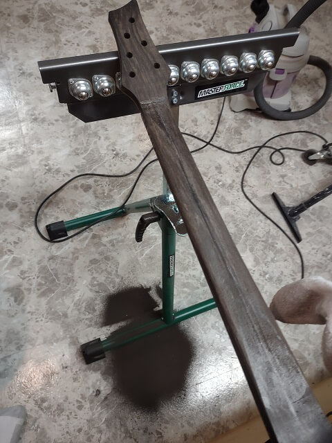
You'll notice an old sock covering the horn of the guitar. There's not a whole lot of room to work the rasp in the body cutaway, so the sock is there to reduce the chance of damaging the horn with an errant stroke of the rasp.
Neck carving is a slow process that makes a lot of sawdust. In the case of an ebony neck, it makes a lot of black sawdust.
The Tundra Boy finished carving the neck, then sanded it to remove the carving scratches. He then stepped away for about a week and spent some time deciding if he was satisfied with the neck profile. I thought it felt OK to me, but after a week he decided he needed to remove some more wood, especially at the edges.
There's always a fear that a person can tweak something too much, which I admit I felt when he announced he was going to carve the neck further. The Tundra Boy was less fearful than I, and proceeded to refine the neck shape.
After he removed more wood and sanded everything smooth, I must admit the neck feels pretty darn good. The overall neck shape turned out very pleasing to the hand. Couple that with the great feel that unfinished ebony has, this neck is going to be very sexy. It feels so good I would keep picking up the guitar just to put my hands around the neck. It's the kind of guitar neck that after holding makes you feel like you need to repent.
The neck carve was the last step in the construction process. Now it was time to apply a finish and then add the hardware.
Return To The Main Music Gallery
This page last updated on 04/02/2024