


All of the construction pictures I took were comprised of the original version of the instrument that still had the neck-through design. After the original neck was destroyed, I neglected to take any pictures of the restoration neck. This is unfortunate, as in retrospect it would have made for an interesting photo-journal of how I was able to salvage this instrument. Nevertheless, here are the pictures I have of the construction.
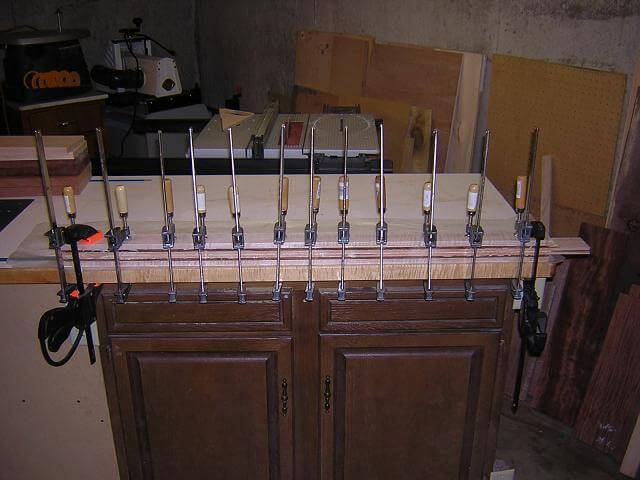
A neck-through instrument starts with building the primary structural "backbone", which is the neck blank. This blank has to be long enough to span the entire length of the bass. This blank is made up of seven layers of wood, comprised of three different types: maple, mahogany and walnut. When gluing up neck blanks, I clamp the blank to my work bench which acts as a guide to keep the neck arrow straight.
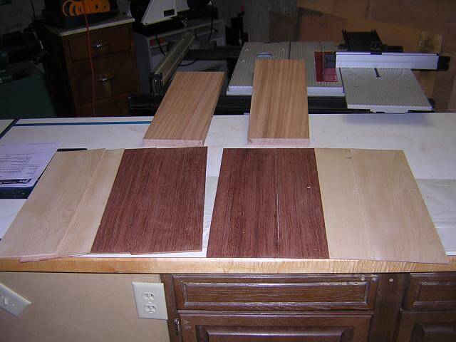
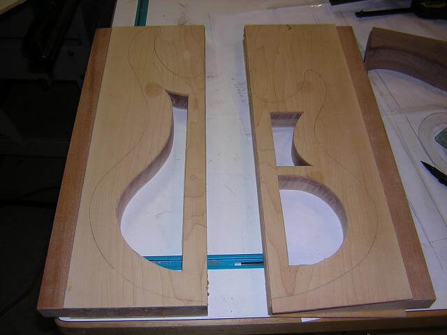
The other portion of the instrument is comprised of the body "wings" which will eventually get glued on to either side of the neck blank. The wings on this bass will primarily be made from 1" of a mahogany core, surrounded by 1/8" pieces of maple, capped on either side by 1/4" of bubinga. Here are the blanks prior to gluing them together to form the wood "sandwich."
Rather than gluing all five layers of the wings together at once, I just glued up the inner layers. This served a couple of purposes: first, gluing three pieces of wood together at once is easier to do than gluing five pieces. Second, and most importantly, by gluing up this inner layer I can easily cut out the control cavity and some weight reduction chambers. The mahogany pieces I used for this bass were very dense and heavy. In order to reduce the weight of the instrument and make it more enjoyable to play for long periods of time, I hollowed out portions of the wings. These hollow areas won't be visible once the instrument is complete.
Some companies refer to these weight reduction cavities as "tone chambers" implying that they make the instrument sound better. The jury is still out on that one. In my opinion, they make the instrument sound a little different. I'm not convinced they improve the tone, although I do think they change the tone slightly. It doesn't mean that the guitar would sound bad with or without them. It would just sound slightly different.
Frankly, nobody in the audience will ever know if your guitar has chambers or not just by listening to you play. They will notice, however, if you fall over halfway through the night because the weight of the instrument finally did you in. So for that reason, I opted to chamber this bass.
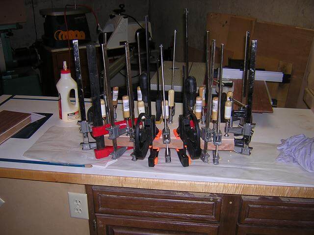
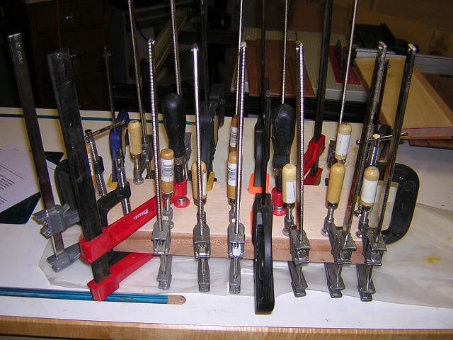
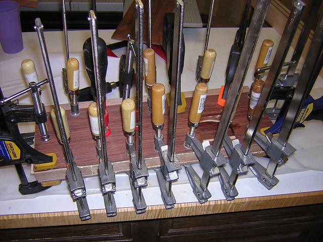
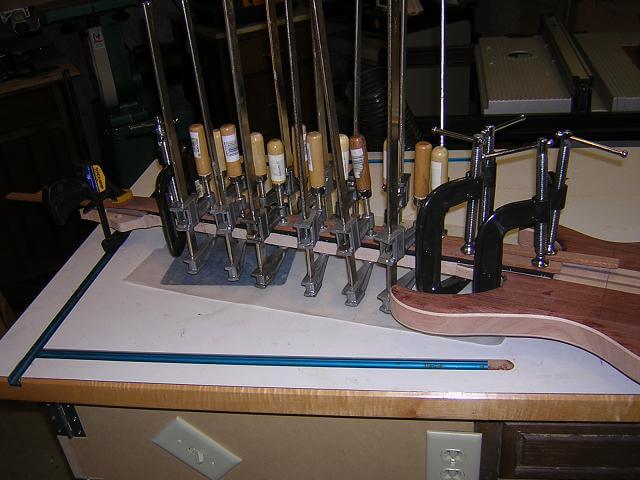
I then did the same thing with the other body wing. And before you ask: no, that's not every clamp I own. It's probably about half of them.
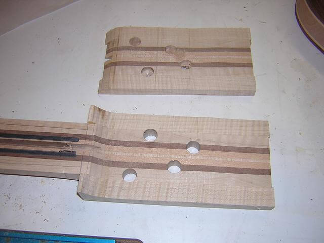
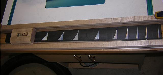
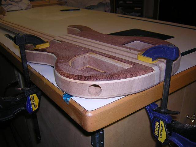
Here is a picture that clearly shows the chambers. The "D" shaped cavity on the lower right is where the electronics for the guitar will go. The other holes are purely for weight reduction. The bubinga pieces will be glued over these core pieces and nobody will be the wiser that the body wings are hollow. I did have to be careful once the bubinga was glued in place to keep track of which side of the piece was which, less I accidentally cut into the chambers.
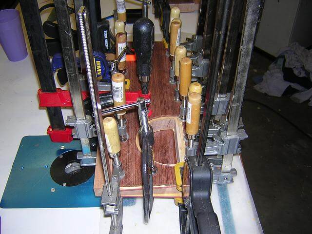
Here the bubinga cap is being glued to the maple/mahogany core. You can see that this cap has a square cut out, which will hold the 9V battery boxes. The boxes will sit inside one of the weight reduction chambers.
Again, I repeated the glue-up for the other body wing. This one will hold the control cavity, which is clearly visible in the picture. I carefully cut out the cavity cover from the bubinga, and set that piece aside.
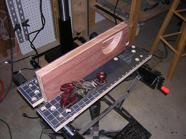
The sides of the body wings that will be glued to the neck blank need to be perfectly straight. I cut them flush on the table saw, then finished truing them with a hand plane. Since I did this, I have obtained a jointer which makes this operation a lot faster. I'm not worried about cutting the other three sides flush, as this will be accomplished when I cut out the body shape.
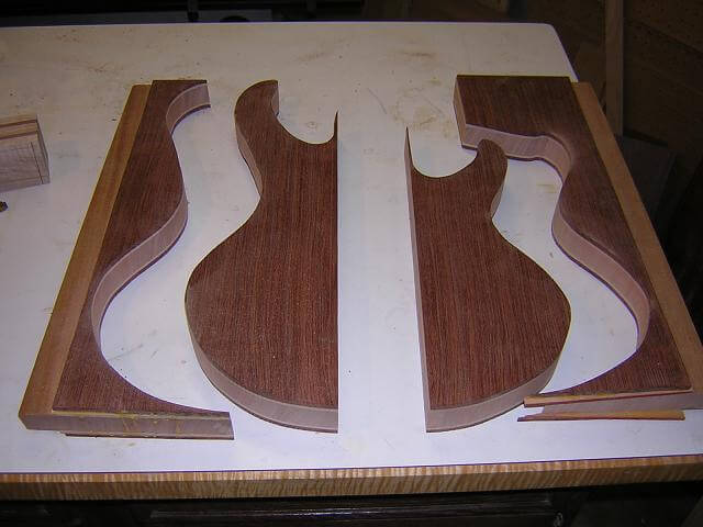
I used my band saw to rough cut the body shape from the wings. I stayed about 1/16" outside the line, as it's difficult to cut directly on the line and the band saw leaves a rather rough cut.
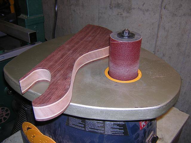
Using my oscillating spindle sander, I then sanded the body wings right up to my outline. This made the body the exact size I wanted, and removed the band saw scratches.
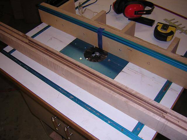
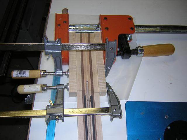
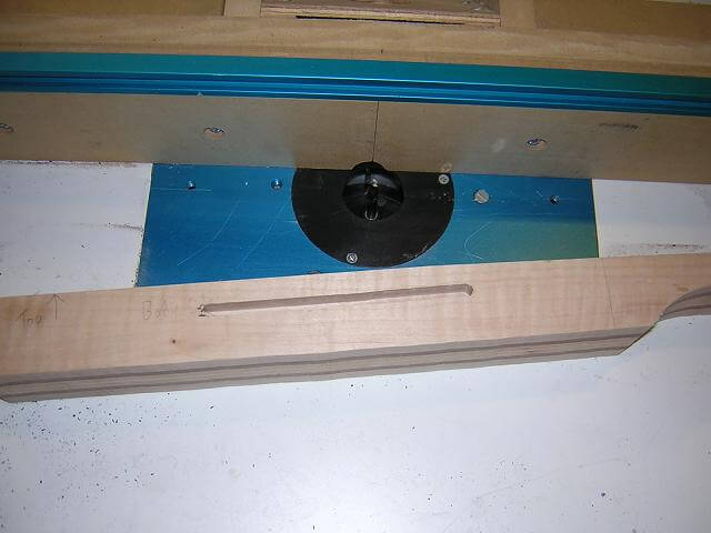
When building an instrument, I usually jump back and forth between different parts. In this case I took a break from the body to use my router table and cut channels down the neck to hold the truss rod, and the carbon fiber rods. The truss rod provides adjustability to the neck. The carbon fiber rods provide rigidity to the neck that should reduce the amount of adjustability that will be needed. As a bonus, carbon fiber is supposed to prevent "dead spots" in the neck, although I have nothing but anecdotal evidence that this is true. I include them in all my necks mainly because it prevents me from lying in bed a night "wondering if..."
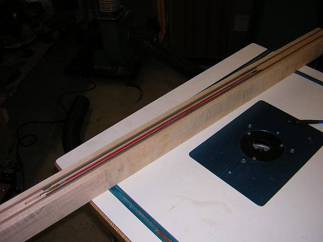
I took a moment to test fit my truss rod and carbon fiber rods fit in the channel.
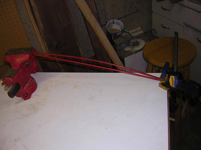
Having experienced a truss rod failure once before, I have learned (the hard way) that it is much easier to find out a rod has a problem before you glue it into the neck. Once it's in the neck, it more than likely won't be coming out without doing some major surgery. So I test my rods by placing one end in a vice and turning the adjustment screw. After testing it in both directions, this rod passed so I feel safe about placing it in my neck.
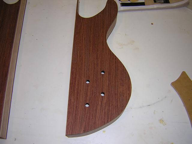
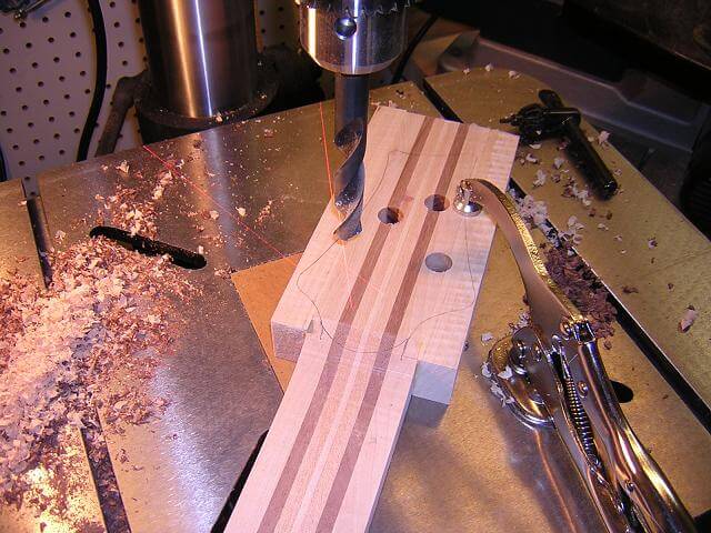
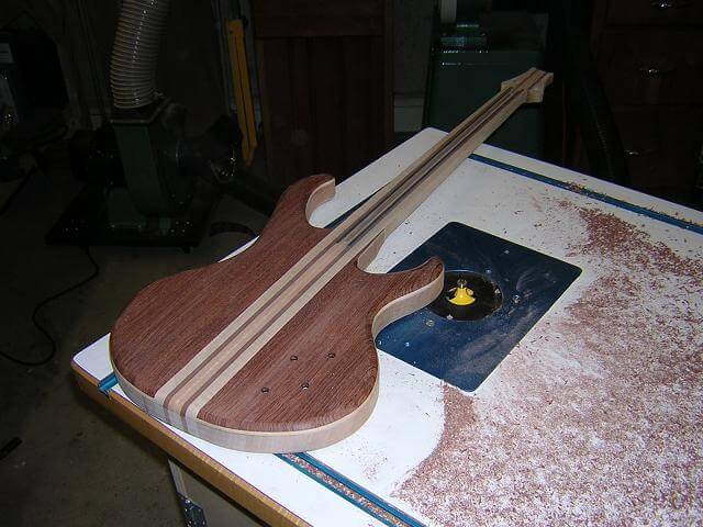
When working on a neck-through instrument, once the neck and body get glued together the instrument can be a little unwieldy when doing certain operations. Because of this I've learned it's easier to do as much as I can with the smaller pieces, prior to gluing them together. In this picture, I have drilled the holes for the control knobs on the front of the instrument.
Many instruments have a neck angle, which means that the neck is tilted back towards the player by a small amount. I describe in detail the reason for doing this on my neck angle calculator page." Accomplishing this on a neck through instrument seems to be a mystery to many new builders, so I am now revealing my secret.
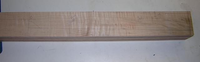
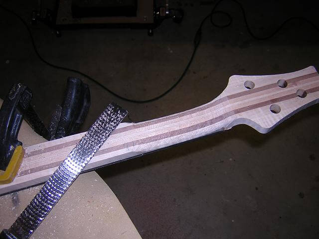
This pencil marks in this photo are a little light, but it shows how I do it. On the body end of the instrument I mark the portion of the neck that will be attached to the body wings at the proper angle. In this case, it was about 2 degrees. Once I cut out the body portion of the neck blank, then glue the body wings in place, it will create my neck angle. I do this on the body end because the body side is shorter and to angle the neck would require an extremely thick neck blank.
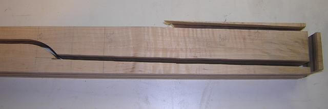
Once everything is marked, I then made the cuts on the band saw. This picture makes the cut lines a little easier to see how I created the neck angle.
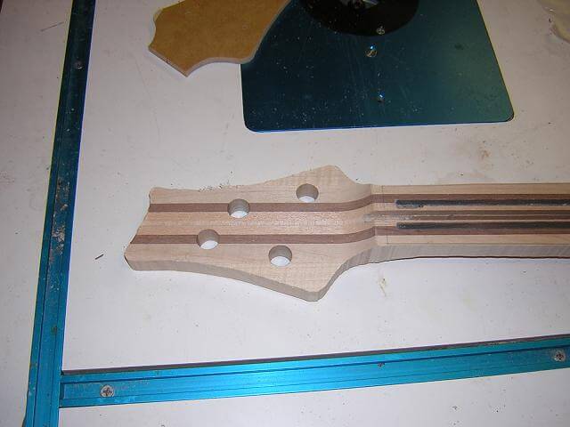
Because the headstock is wider than the rest of the neck blank, "ears" are glued on to either side. This will give proper width to this area for when the headstock is shaped.
I took the opportunity to drill the holes for the tuning pegs. I could have done it later, but I was in the mood.
All of my guitars up to this point have used an angled headstock that utilized a scarf joint. Just for a change of pace I decided to try a "Fender-esque" flat headstock. I think the flat headstock styles are a touch stronger, but the angled headstock gives a little better break angle over the nut. They both can work fine. The big goal in either method is to make the string angle down over the nut to where it wraps around the string post. This keeps the strings from popping out of the nut slot, and reduces the tendency for the string to buzz in the nut slot. Here is a picture of the recessed area of the flat headstock after cutting it away.
I rough cut the headstock to shape at the band saw. As with the body wings, it's hard to get an accurate cut right on a line, plus you have to deal with the band saw scratches. So I made the cut about 1/16" proud.
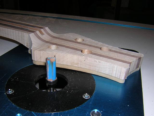
I then used double-sided tape and attached my headstock template to my neck. With a pattern cutting bit in the router table, I trimmed the headstock to final shape. This also removed the band saw scratches.
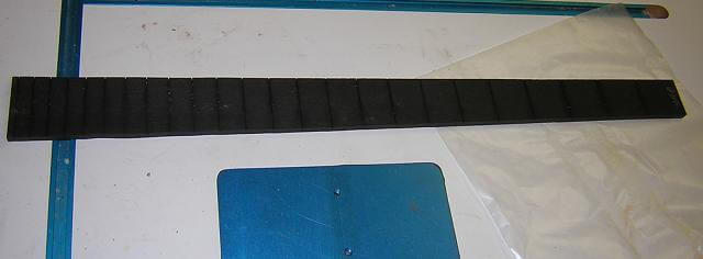
I turned my attention over to the fretboard. This started out as an ebony blank. I cut the fret slots, and then tapered the board to the proper width so the nut was narrower and the body end was wider. The taper cut at this point is rough on the band saw.
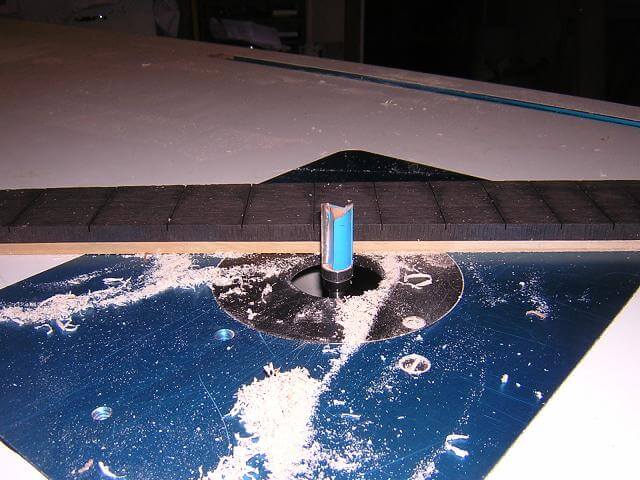
Again, using double sided tape and a flush trim bit in the router table, I attach a known straight edge of a board to the fretboard and trim it to the exact size I want.
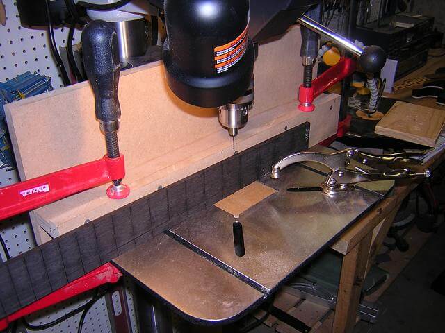
The holes for the side dots (which are the dots most used by players) are drilled at the drill press.
The side dot material is then glued in place. After the glue dries, the excess portion of the material is cut off and saved for use on the next guitar.
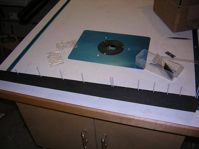
This original neck contained "shark tooth" inlays made of mother of pearl. They looked OK after I had completed the inlay work, but I thought it was a bit on the common side. So when I built the new neck, I used "V" inlays which aren't seen as often. Regardless of the shape, the installation method is identical. I started by correctly positioning the inlays on the fretboard. I then used a dab of Duco glue to temporarily hold them in place. A sharp scribe was run around each inlay to mark the fretboard. The inlays were then carefully pried off and chalk was rubbed on the scribe line to make them more visible.
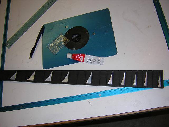
I then used a dremel tool with a very, very small bit to remove the material inside of the scribed lines. This is slow and tedious.
A mixture of slow set epoxy was mixed up, with a dab of black ink to color the glue. The inlays were then glued into the recesses. The black epoxy will hide any minor spots where the recess is ever so slightly larger than the recess. With the blobs of epoxy squeezing out of the fretboard, it always looks terrible at this point in time.
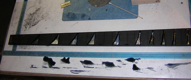
After the epoxy has dried, the glue and inlays can be sanded flush with the fretboard. Most fretboards are not flat on their faces, but have a slight curved radius sanded into them to improve playability (because our hand isn't flat.) I kill two birds with one stone by sanding this radius into the fretboard at this time, which also levels the glue and inlays. For this instrument, I used a 14" radius.
Back to my neck blank, I took care of a detail that is very easy to forget. Because this instrument will have two pickup cavities, there needs to be a way to run the pickup wire from one pickup to the other. With a neck-through instrument, trying to do this after the body wings are installed would be problematic at best. So I took a few minutes and routed a wire channel in the side of the neck. This will get covered up after I glue the body wings in place, but then it will get revealed when the pickup cavities are routed.
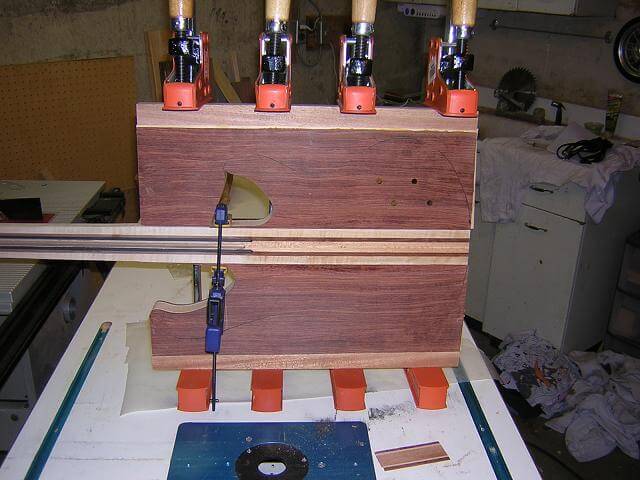
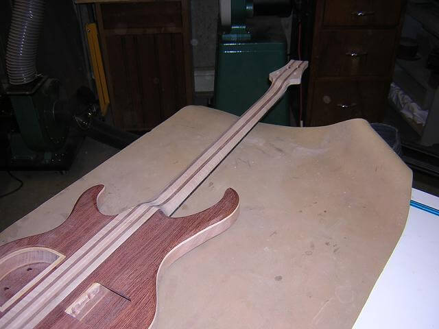
It was now time to glue the body wings to the neck blank. Because the wings were already cut to shape, it would be difficult to keep the clamps in place on the curved edges. To solve this, the scrap wood left over from cutting out the body wings were used as "cauls". This gave me a flat edge on either side to which I can affix the clamps.
No matter how carefully you line things up after gluing, a little sanding is always needed. In addition, because I had cut the body end of the neck blank with the band saw (to achieve the neck angle) I also had to sand to remove the band saw scratches. Didn't take long with some 100 grit paper and I had a nice smooth glue-up.
Playing an instrument with sharp 90 degree angles on the body edges wouldn't be comfortable. So to improve both the comfort and the looks, I rounded the body edges with a 1/2" round over bit in the router table.
After the body edge has been rounded over, I was able to drill the hole for the output jack. I have to do this after rounding the edges otherwise the router bearing would "fall into" the output jack hole and wreck the body. Believe me; you only make that mistake once in your life...
It was now time to glue the fretboard to the neck of the instrument. I make sure to put a piece of tape over the truss rod channel, spread the glue over the face of the neck, and then remove the piece of tape. This prevents the glue from seeping into the truss rod channel and seizing the rod, making it nonfunctional.
In this picture, I had used standard wood glue (PVA) to attach the fingerboard to the neck. I had done this in every instrument I had made up to this point, and in every instance my neck developed a back bow. This is a common problem, and is due to the amount of moisture introduced into the neck by the PVA glue. In all previous instances, the back bow was very slight and was resolved either by string tension or by a minor truss rod adjustment. However, in this neck after removing the clamps the back bow was very pronounced. This resulted in my attempts to straighten it and the subsequent emergence of the truss rod out of the back of the neck.
After this last experience I have stopped using PVA for attaching freboards and have switched to slow-set epoxy. Epoxy does not contain the moisture that PVA has, and therefore does not induce back bow into the neck.
You can see in the picture that I have a couple of strips of wood running down the fretboard to protect the fretboard face from the clamps. When applying clamping pressure it is easy to dent the fretboard. This strip of wood prevents this. I'm not so worried about the back side of the neck, as I will be removing any dents when I carve the neck.
After the fretboard glue had dried and the clamps were removed, it was now time for my favorite part of building the instrument: carving the neck. This is the part of the build that makes most beginners nervous. In fact, some builders either fear or dislike neck carving so much that they choose to purchase their necks pre-made and just attach them to bodies they build.
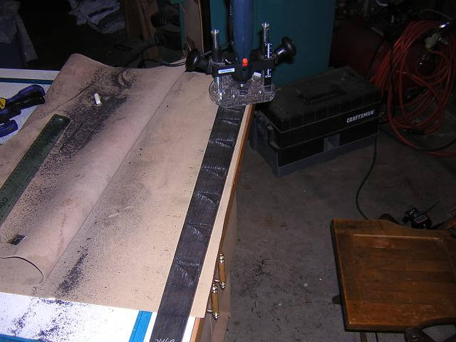
For me, however, carving the neck is the part of the process where you really feel like you're being a craftsman. This is the part of the build where the instrument's personality really makes itself known. I use rasps to do the rough carving work, which leaves a very jagged surface as visible in the picture below. Once the neck is rough carved, I then start smoothing everything out with sandpaper. Carving and sanding a neck until smooth takes somewhere around an hour to an hour and a half. The only real gauge I use for the shape is my hand. I just keep carving and shaping until my hand tells me it's a good neck. It's not fast work, but very satisfying when that formerly square piece of wood now sits as comfortable in your hand as an old ball glove.
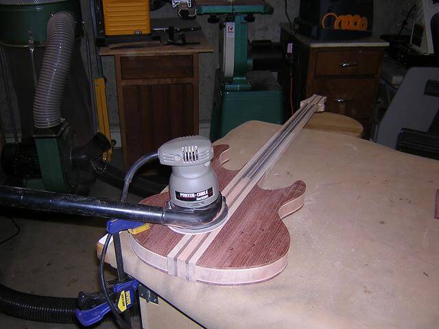
I used to do the neck to body and neck to headstock transitions with rasps as well, but found they weren't as accurate as what I needed in these areas. I since have started to use my oscillating spindle sander to shape these areas. I do the shaping free hand, meaning I'm holding the neck rather than laying on the sander table. The OSS can remove wood very quickly so I need to be careful not to remove too much wood. I can always remove more wood if needed, but it gets quite a bit trickier to put some back if I remove too much.
Now that the neck is completely carved and sanded smooth it is really starting to look like a guitar.
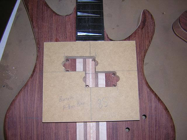
And so we come to the final picture I took during this build: routing the pickup cavities. I created templates out of MDF sized to fit the pickups I am using in this bass. I then affixed them to the front of the instrument using double sided tape, and used my pattern cutting bit to remove the wood where the pickup will reside.
Because pattern cutting bits have a minimum radius of 1/2" (due to bearing sizes) and the pickup corners were rounded at a 1/4" radius, I first had to drill 1/4" holes at each corner of the template. Then, when the pattern cutting bit would remove the remaining pieces of wood I would have properly sized pickup cavities.
As mentioned before, I neglected to take photos of the remaining operations I completed for this build. These consisted of routing the second pickup cavity, drilling the holes for the bridge and the strap pegs, fretwork and applying the lacquer finish. Of course, the entire new neck that I had to build and fit to this body also was done without the benefit of pictures. At least I got the bulk of the build documented.
Return to see the pictures of the completed bass.
Return To The Main Music Gallery
This page last updated on 06/28/2018